
تایمر تاخیر ۱۲ ولتی
۱۲V Time Delay Relay Circuit
Protect your equipments with this tiny 12V time delay relay circuit. The SMPS based power supply of these modern electronic devices is vulnerable to spikes in the mains line so it gives a time delay of one minute before applying power to the device. This prevents deleterious effects due to inrush current and spurious spikes at power on.
Inrush current at power on or power resumes after a power failure can cause unexpected damage in SMPS based power supply of electronic devices. The spurious spike in the power supply when power resumes is due to heavy magnetic flux in the distribution transformer in the mains network. If a short delay is provided, such damages can be avoided. The time delay relay circuit described here is intended for this purpose. It gives power to the device only after one to two minutes of delay after the power is switched on. The circuit is a zener controlled switch.
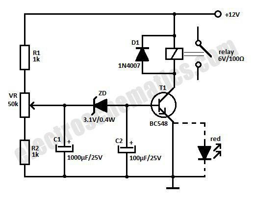
Capacitor C1 charges through R1 and VR. When the voltage in C1 rises above 3.1 volts, zener conducts to trigger T1. The relay connected to the collector of T1 energizes and power will be available through the common and Normally Open contacts of the relay. Relay remains latched as long as the voltage level in the mains is normal. Capacitor C2 keeps the base bias of T1 steady so that relay clicking can be avoided. Diode D1 prevents back EMF when T1 switches off. Red LED indicates the Relay On status. Delay time depends on the value of C1.